Regulation systems for controlled fermentation, freezing out and malolactic fermentation of wine
Regulation systems not only enable recording and control of temperature of juice or mash but enable regulation of temperature by heating during malolactic fermentation of wine too. Cooling as well as heating in tanks is solved using tank duplicators or stainless plates or riffled tubes installed in the tanks.
Version A: cooling and freezing for up to 15 tanks or heating of up to 15 tanks in a set
Version B: heating and cooling for up to 15 tanks in a set
Description of the control system
Version A:
(It is used for control of cooling, freezing up or heating of the tanks. Cooling /heating system is already installed.)
Control system (CS) consists of control unit (CU), its power feeder, drive units with valves and evaluation unit and actuators.
CU and power feeder are usually installed near voltage supply. From this point all drive units units and actuators are controlled and fed. Two colours of cables (white and black) are used for better marking of the lines.
CU is further conected with PC on which it is possible to observe function of the system and to change requested parameters. Data can be recorded and stored.
Heat exchangers for each tank are furnished with 1/2´´ and 3/4´´ controlled with servodrive and evaluating unit.
If at the same tank cooling as well as heating is requested, two servodrives must be installed.
Version B:
( Used for heating and cooling of the tanks. Cooling/heating system is already installed.)
Control system consists of the same components as in version A. CS can operate 1 to 15 servodrives for cooling and the same number for heating but sum of both operation types cannot exceed 15.
CS works with voltage of only 10V and corresponds so to conditions for electrical installations in wet surrounding and is absolutely safe.
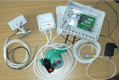
Diagram of control system
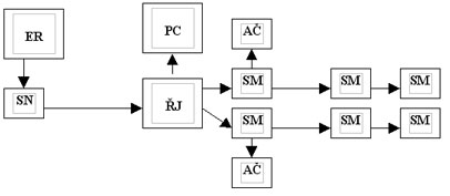
ER – power supply (socket 230V/10A, 50 Hz with braker)
SN – power feeder
RJ – control unit
PC – computer
SM – servodrive
AC – actuator